NOA Arch 1
FPGA
The arch 1 is powered by a Xilinx Zynq Ultrascale+ MPSoC (xczu5ev-sfvc784-1-i). This system-on-chip contains an ARM processing system (PS) capable of running Linux in addition to its sizable programmable logic resources (PL).
PS Peripherals
SSD
The PS is outfitted with an 256GB NVMe solid state drive containing system partitions and user data.
Ethernet

The Gigabit Ethernet port is connected to the PS. See IP Address Configuration.
USB Debug Port

The USB Debug port is connected to a bus controller that exposes four virtual iterfaces.
| Interface | Description |
|---|---|
| 1 | On-board JTAG debugger (compatible with the Vivado Hardware Manager) |
| 2 | PS UART (Linux Shell) |
| 3 | PL UART (TX: AH12, RX: AH12) |
| 4 | Unused |
SD Card Slot

The SD card slot serves two purposes. When powering up or resetting the device, the bootloader will attempt to boot from the SD card if one is present. When inserted after the boot process, the SD Card's partitions are automatically mounted to /mnt/sdcard to transfer data to and from the device.
Reset Button
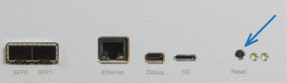
When pressed, the reset button resets the entire system-on-chip (PS and PL).
Status LEDs
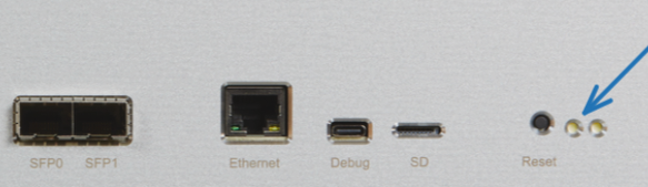
The right-most LED is a power indicator. The left-most LED indicates the machine's status:
| Left-most LED | Status |
|---|---|
| On without blinking | Bootloader and early system boot |
| Blinking rapidly | Awaiting network connection |
| Blinking once per second | Boot complete |
PL Peripherals
Clock Generator
A clock generator provides LVDS clock signals for the PL fabric and high-speed transceivers.
| Descrption | Frequency |
|---|---|
| User Clock (mod_clk) | 100 MHz |
| NVMe Reference Clock | 100 MHz |
| PCIe Clock (Unused) | 100 MHz |
| SFP Clock | 125 MHz |
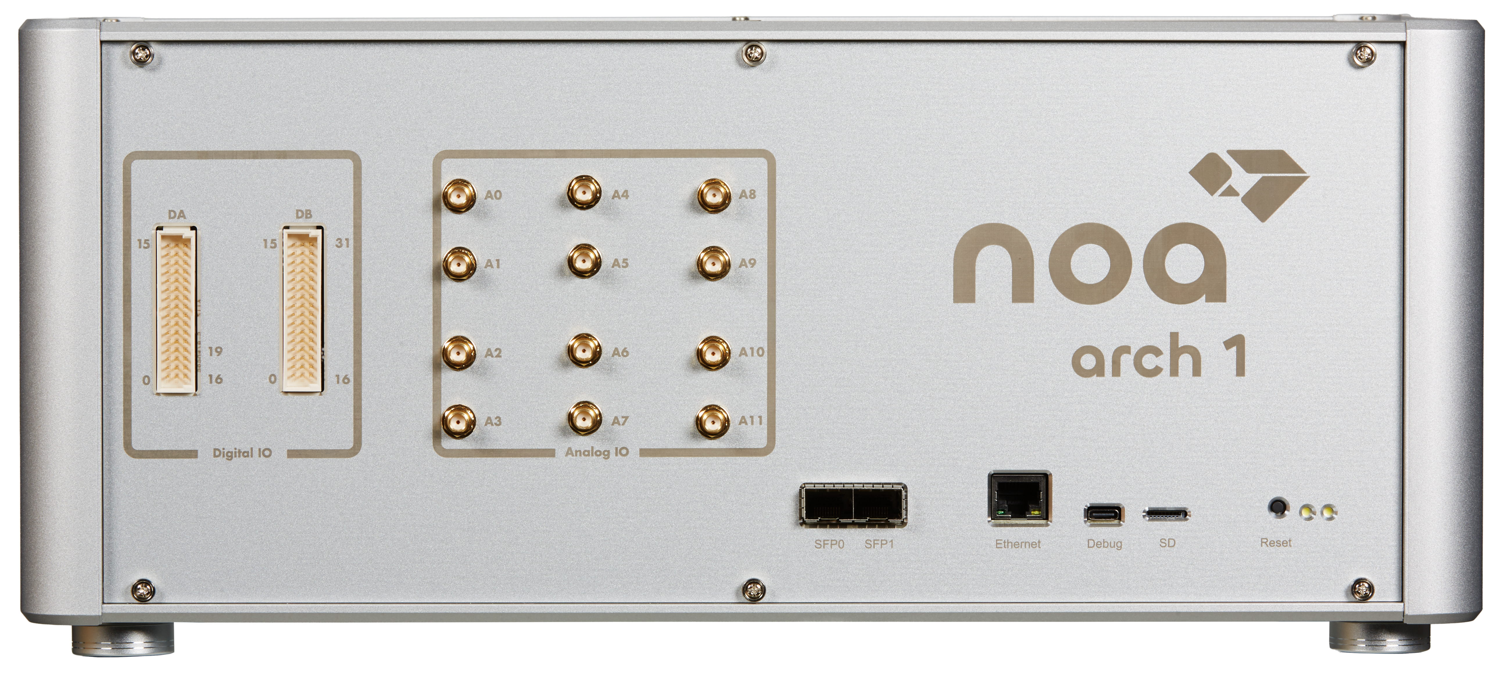
Analog Outputs
The 12 analog outputs are supplied through SMA connectors.
| Specification | Value |
|---|---|
| Resolution | 14-bit |
| Speed | Up to 125 MSPS |
| Voltage Range | ±5V, ±1.25V (software-configured) |
Digital IO
DA and DB are two digital IO modules that provide 3.3V and 5V inputs and outputs to 3-column board-to-board connectors (TE 5650478-5). The left column has pins 0-15, the right column has pins 16-32 on DB and 16-19 on DA. Each pin of the center column is connected to ground.
See the API Reference for configuration.
SFP Transceivers
Two SFP transcievers are connected to GTH high-speed transcievers allow for high bandwidth, low-latency communication between multiple arch 1 devices.