DAQ
The Data Acquisition IP allows for the monitoring of internal FPGA signals by capturing windows of data and sending them to the PS memory through DMA.
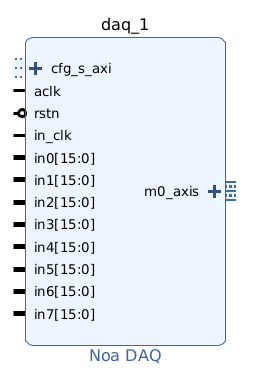


The IP sends a window of data when triggered from its software-configured trigger mode. The acquisition window is of a configurable length, and can include a decimation factor to monitor slow signals.
Warning
The trigger logic interprets signals as signed integers
Port Description
| Port | Description | Clock Domain |
|---|---|---|
aclk |
Configuration and output clock | - |
cfg_s_axi |
Configuration AXI interface | aclk |
rstn |
Active-low reset | aclk |
m(0..4)_axis |
Stream output, each is connect to an AXI DMA IP | aclk |
in_clk |
Input clock | - |
in_wr_en |
Input write enable | in_clk |
in(0..32) |
Input channel data | in_clk |
trigger_in |
External trigger input | asynchronous |
Configuration
| Parameter | Description |
|---|---|
| Input Channel Width | Number of bits per channel |
| Output Streams | Number of output streams / DMA IPs |
| Output Stream Width | Set to 128 |
| Trigger Input | Enable the trigger_in port for the TriggerIn trigger mode |
| Write Enable | Enable the in_wr_en port to selectively write data |
Note
The number of input channels is equal to Output Streams×Output Stream Width/Input Channel Width.
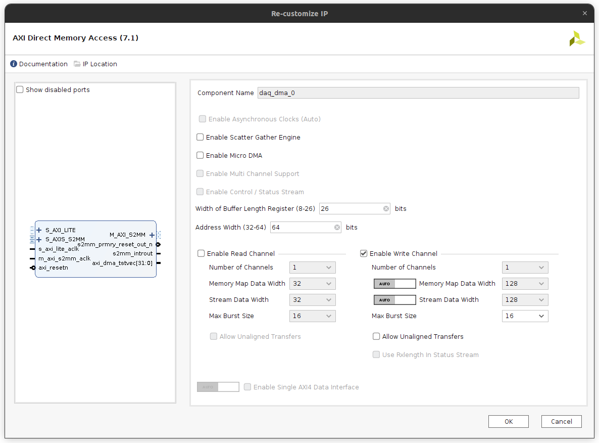
AXI DMA Configuration
Each output stream must be connected to an AXI Direct Memory Access block's S_AXI_S2MM port.
PYNQ Driver
See the API Reference