Analog Out
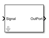
This block is used send a signal to an analog output port, and scales it as chosen in the parameters.
The input signal parameters determine the fixed-point normalization implemented in the bitstream. Signals outside of this range are capped to the minimum / maximum values.
This scaled signal is then linearly mapped onto the output voltage range. The output voltage range can be changed in the IO Setup wizard before and during model execution, whereas the signal range is fixed for a given bitstream.
Ports
| Port | Type | Description |
|---|---|---|
Signal |
input | the signal to transmit |
OutPort |
output | the signal after scaling (double for Simulation, 32 bits signed for HDL Generation) |
Parameters
| Parameter | Description |
|---|---|
| Input Signal Mimimum and Maximum | minimum and maximum values of the input; if the input is above or below, it is capped to the minimum or maximum |
| Output Voltage Mimimum and Maximum | minimum and maximum values of the output; if the input is above or below, it is capped to the minimum or maximum |
Target Interface
Connection and interface of this block
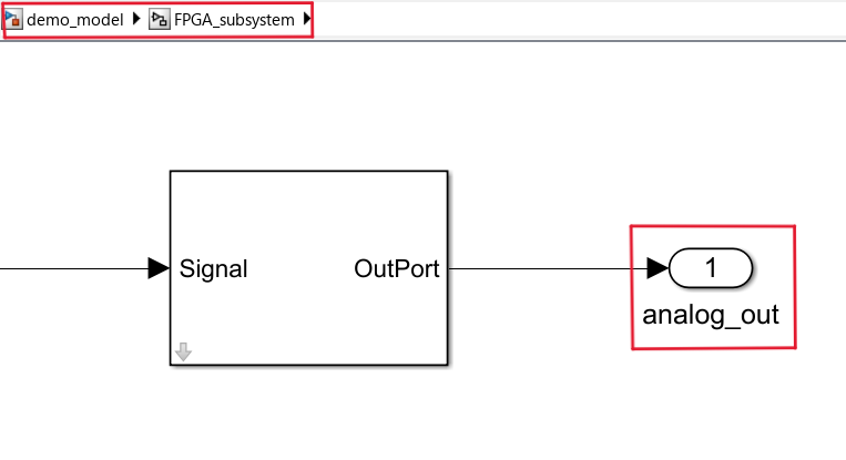
Directly connect OutPort to an output port of the FPGA subsystem, like below.
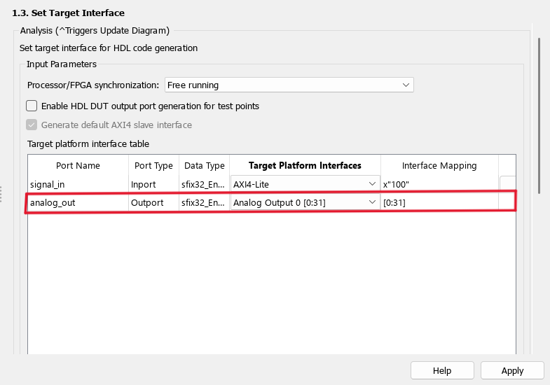
Assign it to an Analog Output interface in the interface mapping (see Generation of the Bitstream file, step 1.3 in the Workflow Advisor; and you need in step 1.2 to choose the number of analog outputs to match your block design).