Connection to your device and implementation
When the Bitstream and the interface are generated, you can start using them to connect you device and programm it.
First, power on your hardware and connect it to your PC through an Ethernet cable. Click on the NOA tab at the top (see below), and follow the next steps.

- Click on "Set Target URL" and enter your hardware's IP address.

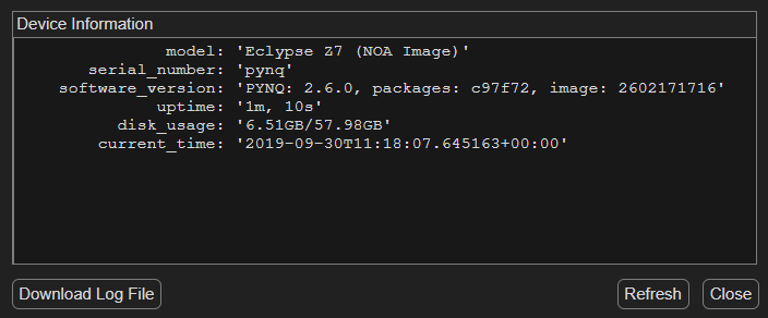
- Then click on "Connect". The "Disconnect" and "Device information" buttons should be clickable now. If you click on "Device Information", you should see a new window appear with the following informations: the model of the device, its serial number, software version, uptime, disk usage, and the current time of the device.

- Then click on "Select .bit File" and "Select .hwh File". The files should already be selected, but check that they're the right ones. Then click on "Load Bitstream" to load your design on you board
 .
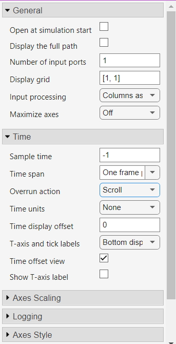
- Next, you have to parameter several things. The scopes you're using to monitor your outputs need to be setup in a particular way to properly visualize the signals. Click on the scope and go the Settings, you should see the window below appear. In "General", choose the Input processing as "Columns as channels (frame-based)", so that one frame appears at a time on your scope. Then in "Time", choose the Time Span as "One frame period", and the overrun action as "Scroll".
- You also need to Setup the DAQ Channels, by clicking on the "Setup DAQ" button in the NOA tab.

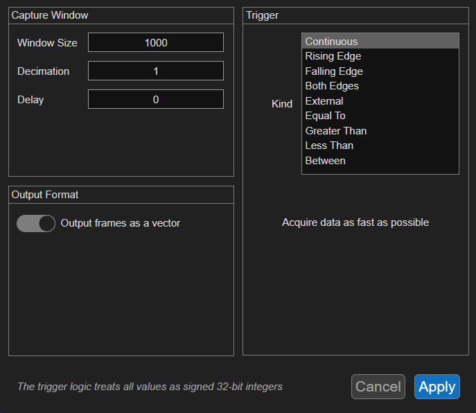
It will open the window below. In the "Capture Window" section you can modify the window size, so the number of values in one frame. You can also modify the "Decimation" parameter, which determines the number of values sampled in this frame: if decimation = 5, 1 out of 5 values in the frame is sampled. You can also modify the type of trigger used to display the signals.
Lower values of decimation ensure a better precision, but can slow down the acquisition process and worsen the quality of the signal displayed. A bigger window size allows you to see a bigger time frame, but also slows down the process.
When you're done, click on "Apply".
- Then you can setup the IOs, by clicking on the "Setup IOs" button.

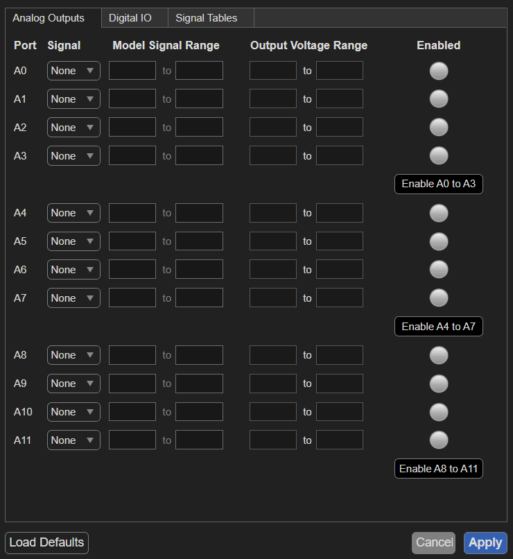
- The Analog Outputs tab is used to change the settings of the outputs of the FPGA Subsystem that have been configured as Analog outputs previously (Step 1.3 of the Workflow Advisor, presented in the page: Generation of the Bitstream file), although the output voltage range and model signal range should already have been chosen in the parameters of the AnalogOut block preceding the output port. Do not forget to enable the outputs!
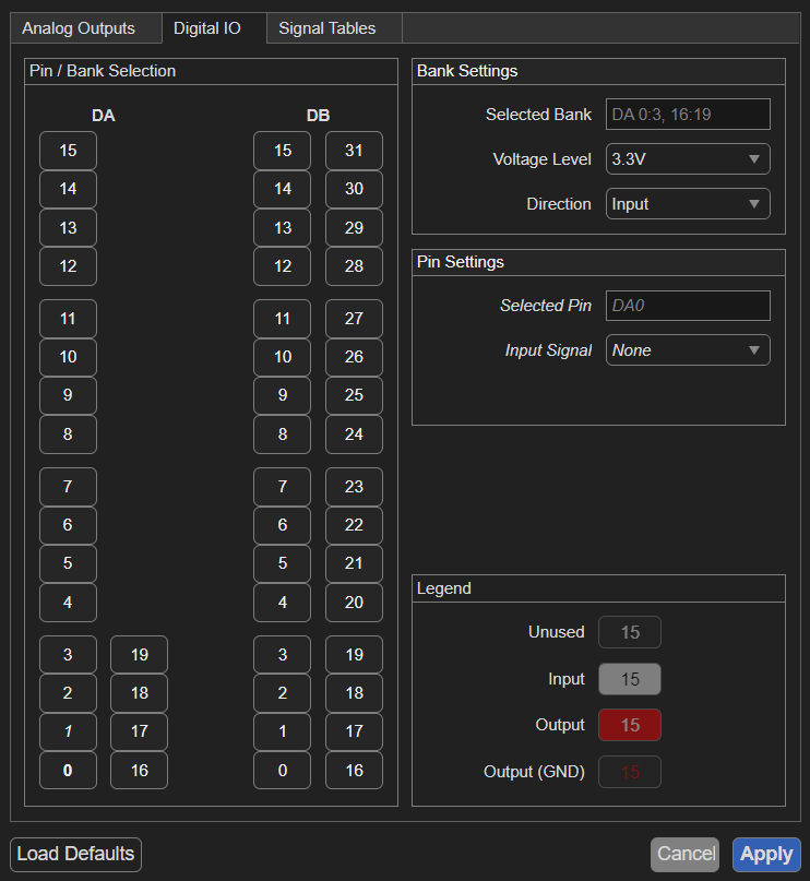
- The Digital IO tab must be used when you have digital inputs or outputs in your FPGA subsytem. It allows you to assign these signals to physical pins, and to choose their voltage level. The pins are grouped by 8: pins of a same group cannot have different directions, they're all either inputs or outputs. If a signal has several bits, it's possible to assign individually each bit to a pin.
- Finally you can click on "Run", and you can modify your inputs and visualize your outputs as you want!

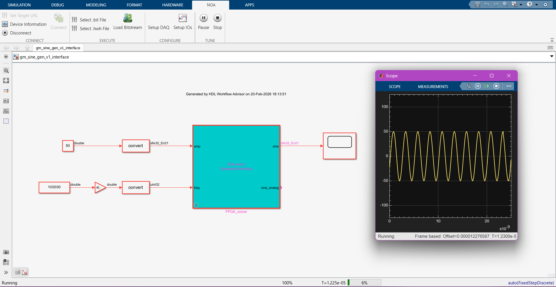
Here for exemple, you can see that the Simulink interface allows to visualise the output of a sinus signal generator, that is acquired on a DAQ Channel, in a very quick and simple way.
Note that you can pause or stop the execution when needed, with buttons in the NOA tab, and you can disconnect your device when you're done, by simply clicking on the "Disconnect" button as well.
