Generation of the Bitstream file and the Simulink interface
Once you're done with your design and wish to implement it on hardware, you have to follow these steps:
- First, run the following command in your Matlab Command Window; it is necessary to make Vivado reachable for the code generation (adjust the path to your Vivado program file):
hdlsetuptoolpath('ToolName', 'Xilinx Vivado', 'ToolPath', 'C:\Xilinx\Vivado\2024.1\bin\vivado.bat')
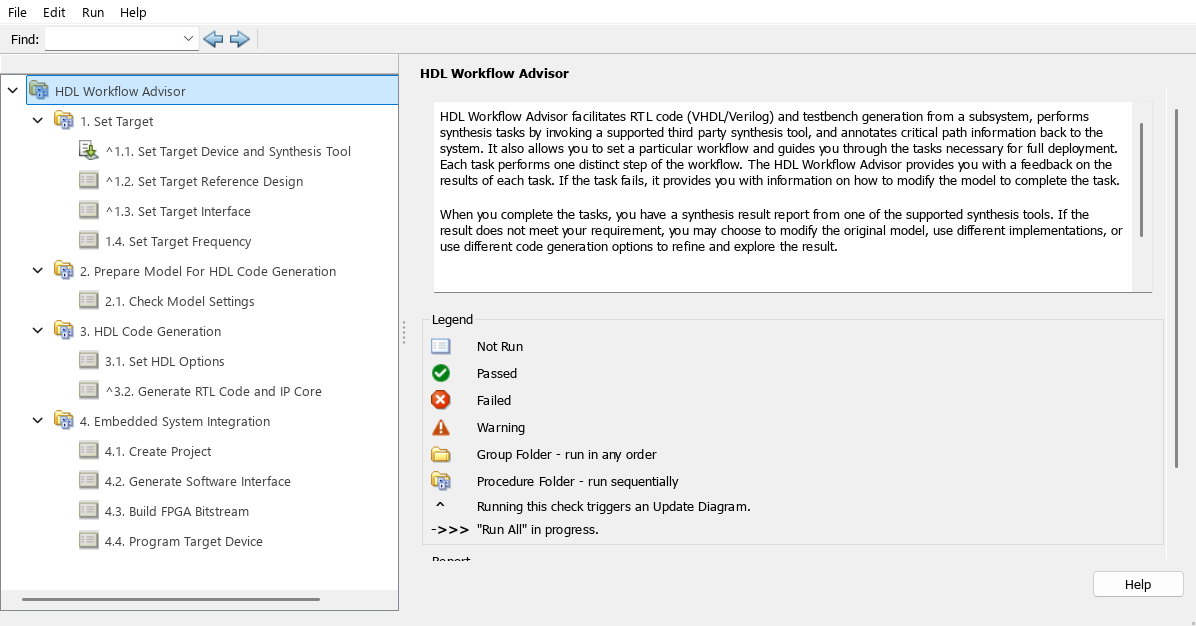
- After that you can click on "Workflow Advisor" and it should open the following window (it can take some time).

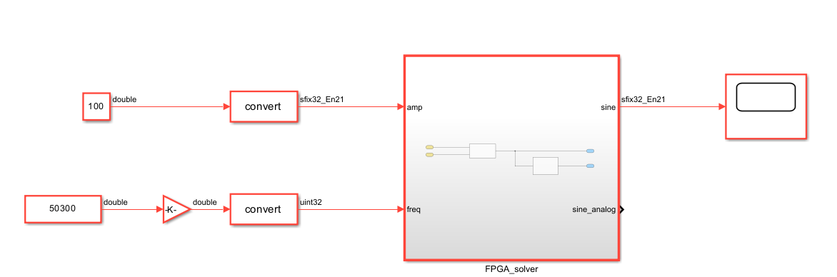
There are various parameters you should check here. Here one of the projects linked in our Examples page, the sinus generator, is used as example.
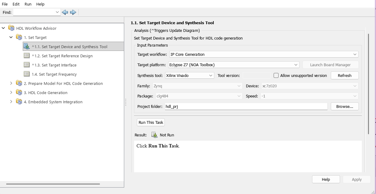
- In 1.1 verify that the Target Platform matches your hardware. Here, the Eclipse Z7 is used but it could also be the NOA Arch 1 platform. The mention "NOA Toolbox" has to appear next to the name of the platform. Select Xilinx Vivado as Synthesis Tool. You can also choose the name and location for the generated project (by default, it will generate it in the folder you have opened in Matlan main window). Once you're done click on "Run This Task" (repeat this for each of the next subsections). A green validation icon is displayed to the left of all the task that were run successfully.
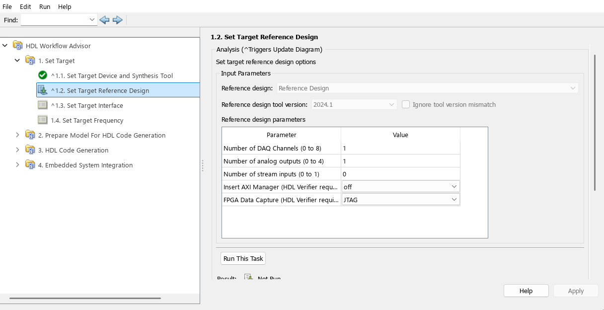
- In 1.2 choose the number of DAQ channels, of analog outputs, and stream outputs, as you need for your design. In the sinus generator example, there are two outputs: one that is acquired through a DAQ Channel, so that I can visualise it directly on my PC, on the interface that we are going to generate, on the Simulink scope. The other output is directed to of the Analog outputs of the board. So here we choose 1 DAQ Channel and 1 Analog Output.
- In 1.3, you have to configure an interface for each of your ports. Here there are two inputs, on top of the two outputs mentionned before. In the "Target Platform Interfaces", each of them has to be associated with the right type of interface (AXI4 Lite, DAQ Channel, etc...).
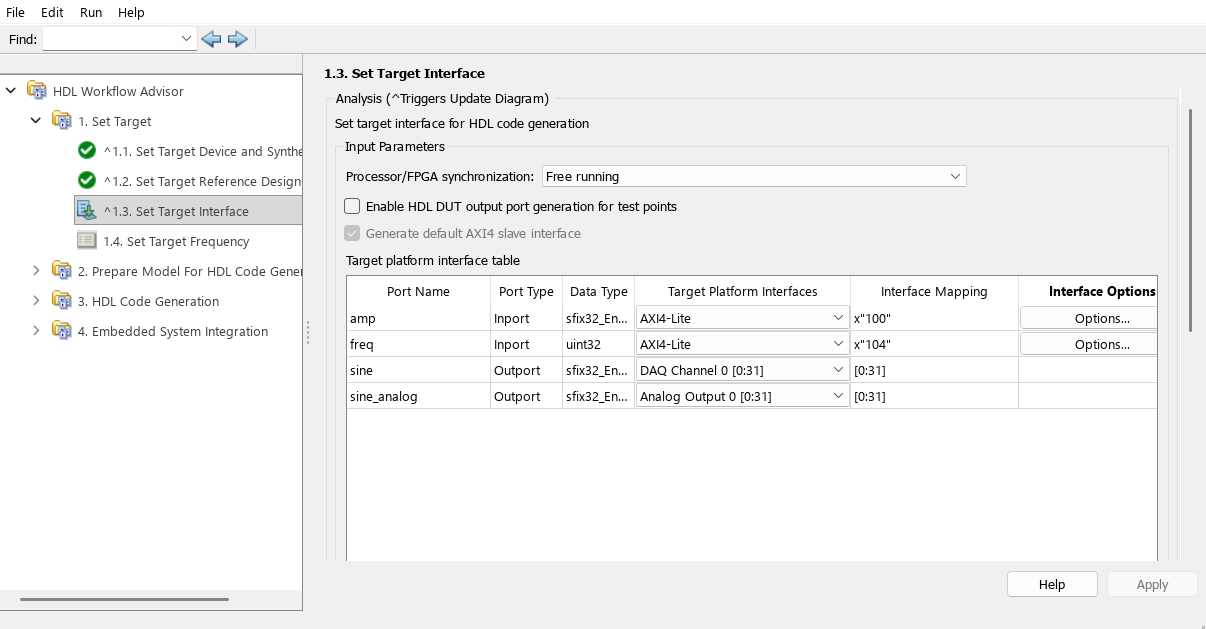
- In 1.4, enter the working frequency of your target device.
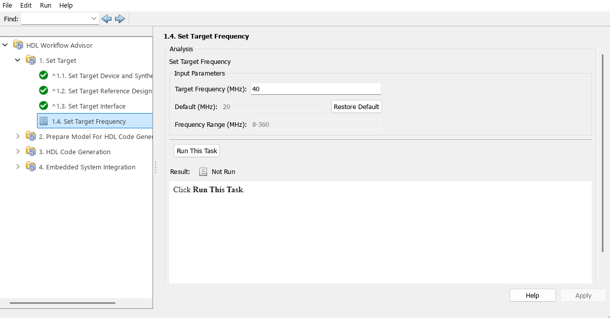
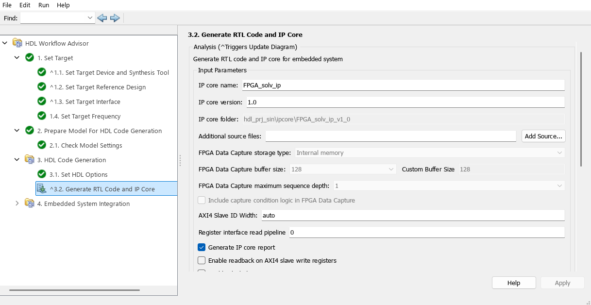
- You can then run the task in 2.1, 3.1 and 3.2. In 3.2 you can modify the name of your IP and indicate its version. You can also run 4.1.
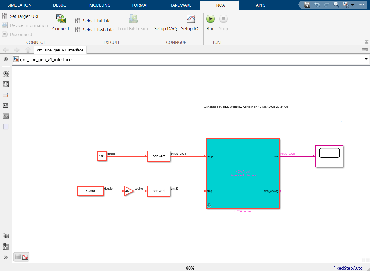
- In 4.2, verify that the "Generate Simulink software interface model" option is checked. A new window should open with the generated Simulink interface (see exemple below). Note that you will perhaps have to dezoom to see the interface. Save it.
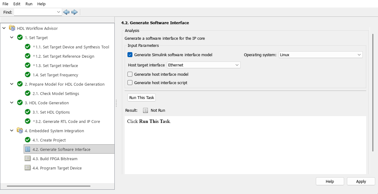
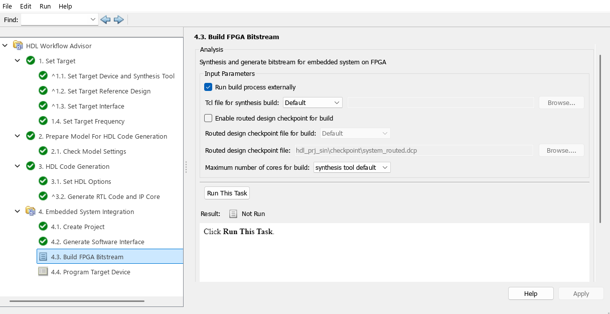
- Finally you can run task 4.3. Note that if the "Run build process externally" option is checked, the process will run in an external command prompt, and you will be able to see its progression. This task can take a few minutes. 4.4 is not necessary.
You can now go the the next step: connecting your device and programming it.