Three-phase sine generators
Available at
This example is located in the folder named three_phase_generators, and contains 3 different versions of a same project: a FPGA programm able to generate a three-phase sine signal. They all produce the same results, and have the same inputs and outputs, but operate in different ways.
Info
They were developped for the Eclipse Z7 board, but may be used on NOA Arch 1 as well.
For all versions
Description
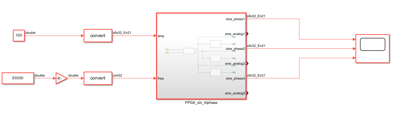
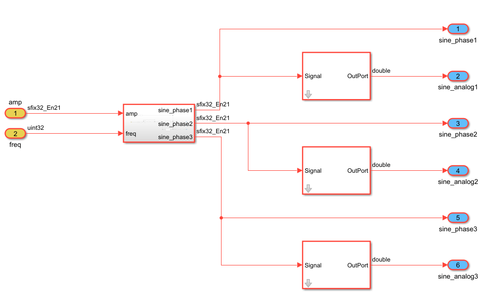
This design has two input ports: one to control the frequency of the waves and the other their amplitude. The three sine waves are then put on six ports, with two ports for each wave: one interfaced to a DAQ Channel, so that it can be seen on a scope on the generated interface, and the other to a physical analog output of the hardware.
The second wave is 2pi/3 ahead of the first one, and the third wave is 2pi/3 ahead of the second one, forming a three-phase signal. It is produced continuously.
For the analog ports, an AnalogOut block is used to scale the input signal to the output voltage. The input signal is in a -300 to 300 range and the output voltage is between -3V and 3V (amplitude divided by ten).
Ports
| Port | Direction | Interface Type | Description |
|---|---|---|---|
amp |
input | AXI4-Lite | the amplitude of the output signal (sfix32_En21) |
freq |
input | AXI4-Lite | the frequency of the output signal (uint32) |
sine_phase1 |
output | DAQ Channel 0 | the first sine phase of the signal, redirected to the host computer (sfix32_En21) |
sine_analog1 |
output | Analog Output 0 | the first sine phase of the signal, redirected to an analog port (sfix32_En23) |
sine_phase2 |
output | DAQ Channel 1 | the second sine phase of the signal, redirected to the host computer (sfix32_En21) |
sine_analog2 |
output | Analog Output 1 | the second sine phase of the signal, redirected to an analog port (sfix32_En23) |
sine_phase3 |
output | DAQ Channel 2 | the third sine phase of the signal, redirected to the host computer (sfix32_En21) |
sine_analog3 |
output | Analog Output 2 | the third sine phase of the signal, redirected to an analog port (sfix32_En23) |
Simulink Interface
First, in the Matlab command window write period = num, where num is the working period corresponding the frequency set later in step 1.4 of the Generation of the Bitstream file process. The blocks in the design work at the period named "period", so it is necessary, to have the design work at the proper frequency.
To implement this design on hardware, you'll need to follow the steps in the Generation of the Bitstream file page, to generate the bitstream file and the interface.
Once this is done, the Simulink interface will look like this:
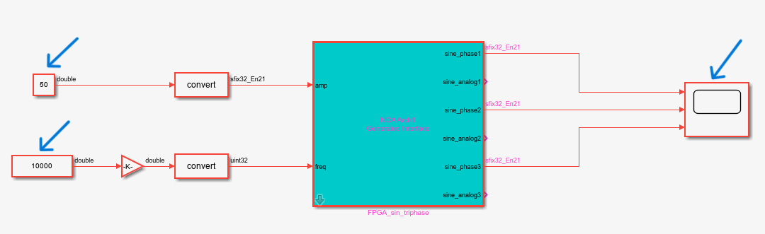
Follow the steps presented on the Connection to the device page, and you will be able to visualize in live on the scope (on the right of the interface), the signal produced on your board (do not forget the settings for the scope).
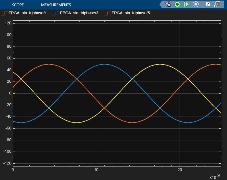
Modifying the two constant blocks on the left will change directly the frequency or the amplitude of the output (in these example pictures, the frequency is 10kHz and the amplitude is 50).
Three-phase generator version 1: sine_gen_triphase_v1
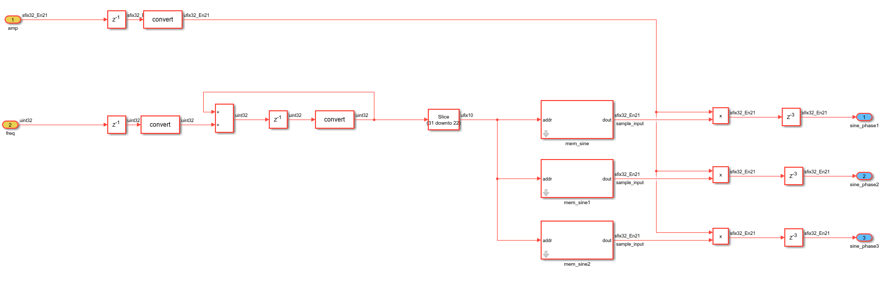
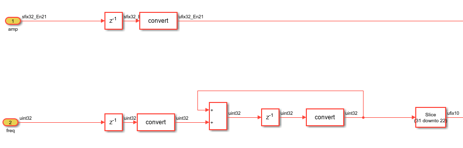
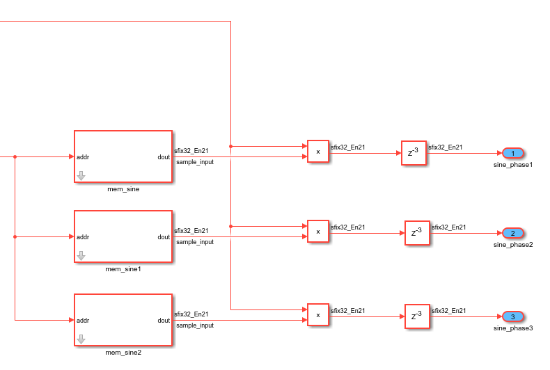
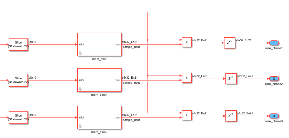
The signal is produced using three RAMs containing values of one sine period. The difference between them is that their starting values are not the same: the first memory begins at sin(0) and ends at sin(2pi), the second one starts at sin(2pi/3) and ends at sin(2pi+2pi/3), and the third one starts at sin(4pi/3) and ends at sin(2pi+4pi/3).
A single counter, connected to the three RAMs, is used to read these values one by one. The value of the freq port determines the number of counter cycles needed to go from one value to the next, which decides of the frequency of the produced wave. Then it is multiplied by the value of the amp port, to modify its amplitude. Finally the three sine waves are redirected to the their respective output ports.
Three-phase generator version 2: sine_gen_triphase_v2
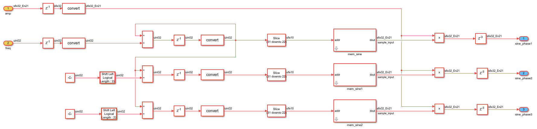
For this version, the signal is also produced using three RAMs containing values of one sine period, but this time they're identical, with values starting at sin(0) and ending at sin(2pi).
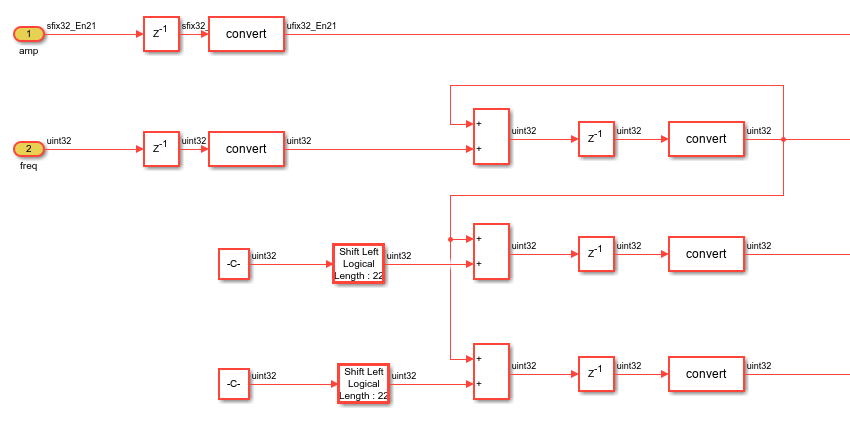
Three counters are used to read the values of these memories, each with different initial values to obtain the 2pi/3 offset between each sine. But the increment for each counter is the same, to have the same frequency for the three phases. The freq and amp ports are used like in version 1 to modify the frequency and amplitude.
Three-phase generator version 3: sine_gen_triphase_v3
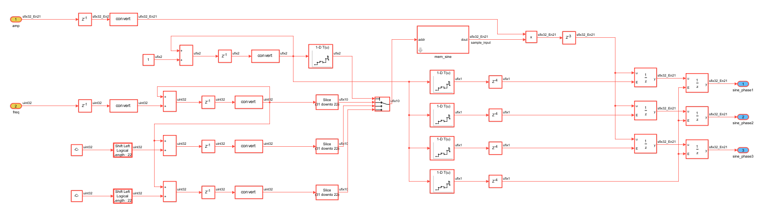
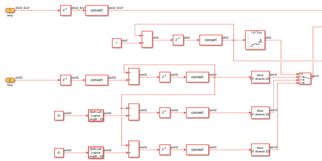
This third version is more optimized, ressource-wise, than the two previous ones, because it only uses one RAM instead of three. This RAM is identical to the ones used in the version 2. The counters used to read the values of this memory are the same as in version 2 as well.
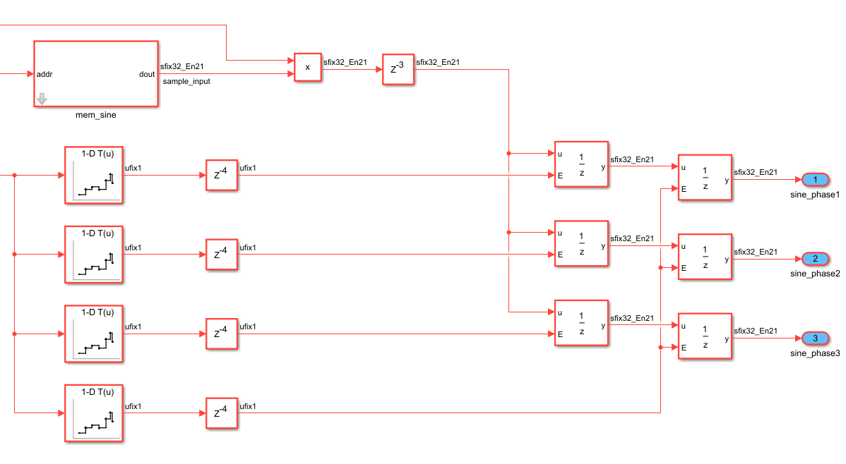
The counters are connected to a 3-ports Index Vector block, which chooses the values of one of its input port to be redirected to its output according to a fourth input port, the control port. The control port is connected to a four-states state machine, alternating between 0, 1, 2 and again 0. The idea is to use the first three states to choose counters one after the other to read one value in the RAM, so first the value read is the one indicated by the first counter, then it is the value indicated by the second counter, etc...
The value are then stored in three separate registers, modeled by "Unit Delay Enabled Synchronous" blocks. The fourth state of the state machine enables the values to go to the output ports, so that the three signals are synchronous.
This design produces less precise sine waves as the two others.