ARINC 429 Word Converter
Available at
This example is located in the folder named "arinc429" and contains three Simulink models, named "ARINC429_converter_v1", "ARINC429_converter_v2" and "ARINC429_converter_v3", that implement a part of the ARINC 429 protocol for avionics communications. These models take as input ARINC 429 words and outputs the corresponding electrical signal.
The first version outputs the electrical signal for a single ARINC word in a loop, while the second one outputs a list of different words. The third one adds to the second a decoder that converts the electrical signal back to the ARINC word.
More informations on the ARINC 429 protocol are included below.
Informations on the protocol
ARINC 429 is a serial communication protocol widely used in commercial aircraft to exchange data between avionics equipment, such as flight computers, navigation systems, displays, and sensors. The protocol uses one-way communication, meaning that one device, the transmitter, sends data to one or more receiving devices. If bidirectional communication is required, two separate ARINC 429 links are used. Here we simulate a single link.
Data is transmitted as 32-bit words, in the order from Bit 1 to Bit 32, where each word contains:
- A label (8 bits) identifying the type of information being sent (e.g., altitude, airspeed, heading).
- A Source/Destination Identifier (SDI) (2 bits), which can identify the source or intended receiver.
- A data field (19 bits) containing the actual measurement or information.
- A Sign/Status Matrix (SSM) (2 bits) indicating the validity or status of the data.
- A parity bit (1 bit) used for error detection.
Electrically, ARINC 429 uses differential signaling over a twisted pair of wires, often named A and B. The signal on B is the reverse of the signal on A, and the receiver detects the voltage difference between the two, rather than measuring each wire individually.
The electrical signal uses bipolar return-to-zero (BRZ) encoding, with three voltage levels:
- Logic 1: approximately +10 V differential (A at +5V and B at -5V)
- Logic 0: approximately −10 V differential (A at -5V and B at +5V)
- NULL state: approximately 0 V differential between transmitted bits (both A and B at 0V)
The models presented here make only the conversion from the 32 bits word to the electrical signal, and can't encode the message into the 32 bits word.
See below for an example of the transmission of an ARINC word; the featured signal is the differential between the two wires (source: Wikipedia)
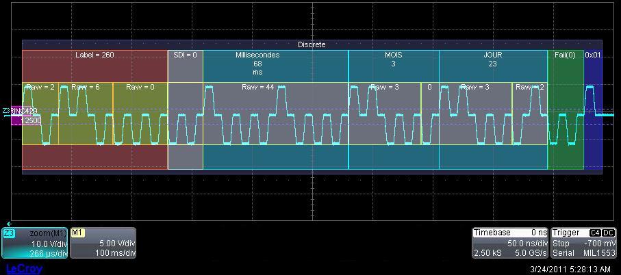
The protocol supports two standard transmission speeds: 12.5 kbit/s and 100 kbit/s.
You can find the complete specifications on the Internet, in the ARINC 429 documentation.
Data
The second and third versions use a list of ARINC 429 words that are contained in a Matlab file, included in the folder, named "arinc_altitude". It contains ARINC words in their 32 bits format that represent messages with altitude values, but the exact meaning of these messages is not important for the following examples. See the ARINC 429 specification to decode the values transmitted.
ARINC 429 converter first version: ARINC429_converter_v1
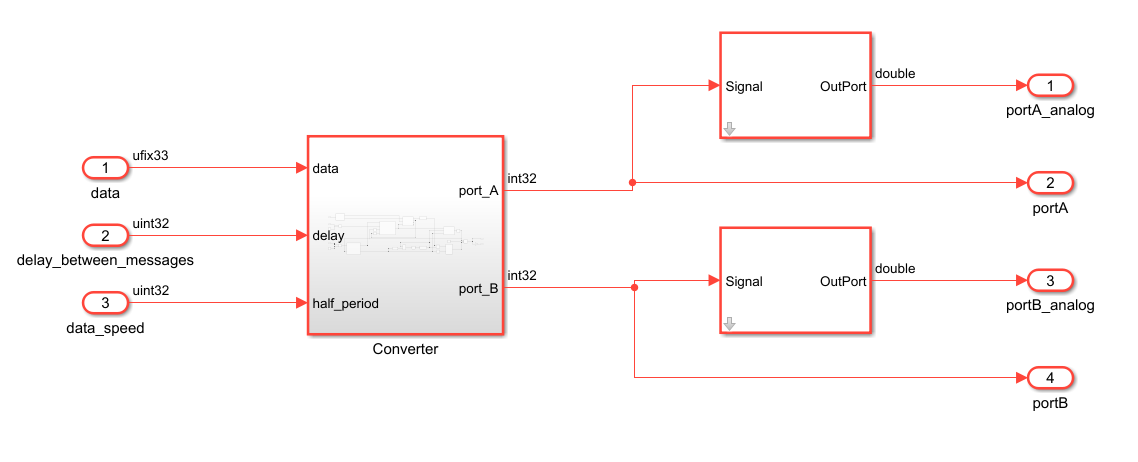
This design has two input ports: one that takes as input the ARINC word to convert, and another to control the output speed of the converted word, in bits per second. The electrical signal of the converted word, produced in loop, is then put on four output ports, with two ports for wire A and two for wire B: one interfaced to a DAQ Channel, so that it can be seen on a scope on the generated interface later, and the other to a physical analog output of the hardware, so that it may be used another device for example.
The differential between the two signals on the DAQ channels is also calculated and rescaled (by multiplying it by 5) accordingly to the ARINC 429 specifications, which asks for signals in the ±5V range on each wire.
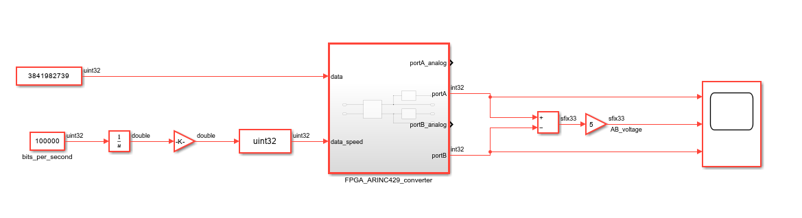
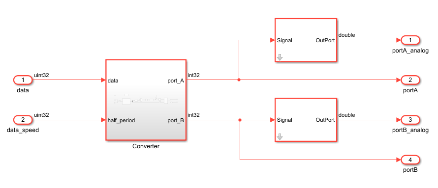
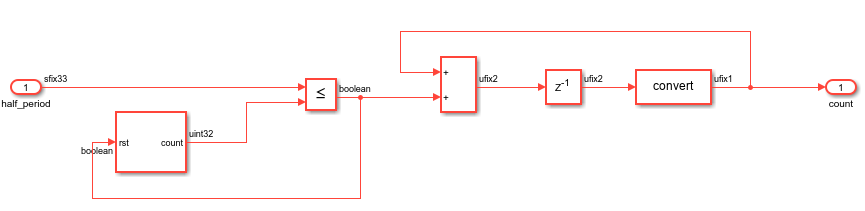
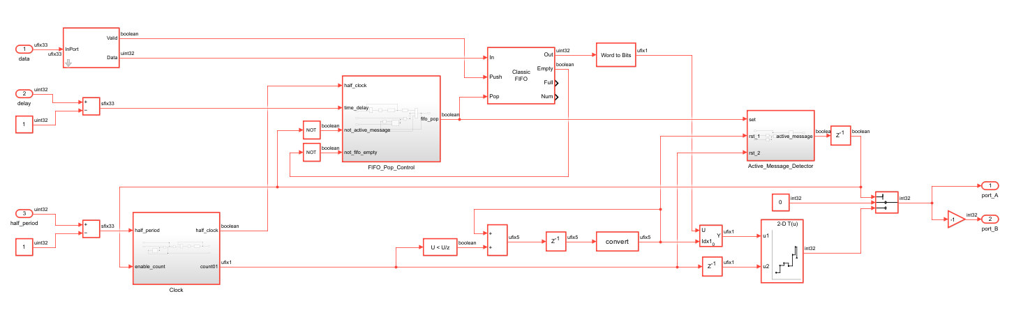
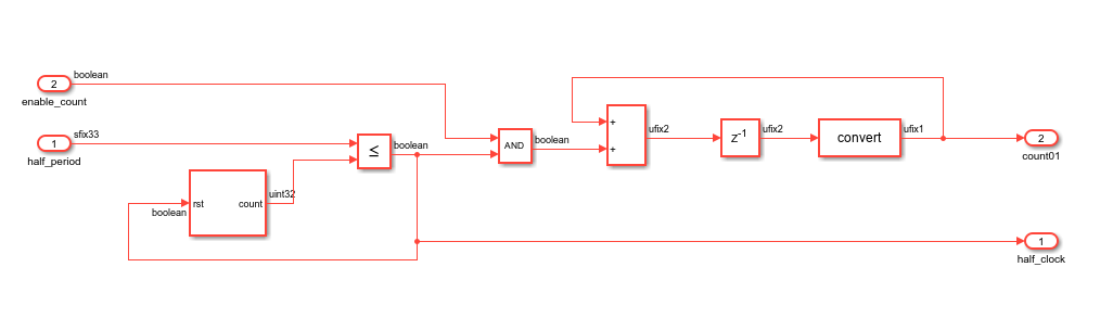
The electrical signal is produced in the following way: the chosen data speed is used to configure the period of a clock, which is half of the period needed to encode a single bit of the ARINC word. Indeed, a word is encoded in two parts: first the logic 1 or 0, and then the null state. The input ARINC word is converted to a vector of bits, and each bit is turned successively to the corresponding signal (1 or -1 for a half-period, then 0 for another half-period) using a Lookup Table, the clock and a 0 to 31 counter used as index for the bit vector. Finally, the signal is redirected to the output corresponding to the wire A. The output for the wire B is simply the same signal but reversed (multplied by -1).
For the analog ports, an AnalogOut block is used to scale the input signal to the output voltage. The input signal is in a -1 to 1 range and the output voltage is between -5V and 5V, to match the ARINC 429 specifications.
This voltage range can of course be modified later through the interface, in the "Analog Outputs" tab of the IOs Setup.
Encoding
The ARINC word chosen is 3841982739 in decimal, which in binary is 1110 0101 0000 0000 0000 0001 0001 0011.
- Label: 00010011
- SDI: 01
- Data field: 0010100000000000000
- SSM: 11
- Parity bit: 1
See the ARINC 429 specification to understand the information transmitted.

ARINC 429 converter second version: ARINC429_converter_v2
This design is very similar to the first one, but instead of converting a same word repeatedly, it converts a list of words, received through a Stream Interface. It has the same input ports, that have the same role as before, except for an additional port, that controls the time delay between each output words. The output ports are the same, and the analog signals produced can be sent to and used by another device, for example, that will be able to decode the original ARINC messages.
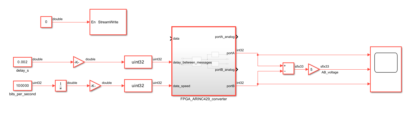
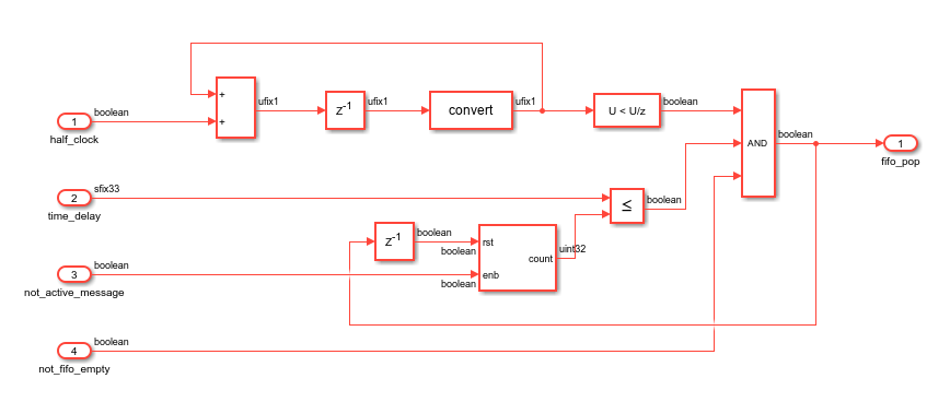
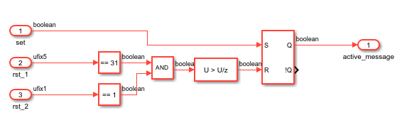
The electrical signal in itself is also produced in the same way, but some elements were added. First a FIFO (of size 1024) is needed to hold the values received from the Stream. It outputs the next value in synchronization with the clock controlling the output signal, when the previous message has been completely converted and the time between two messages equals the chosen delay. A subsystem determining whether a message is currently being converted has also been added.
ARINC 429 converter third version: ARINC429_converter_v3
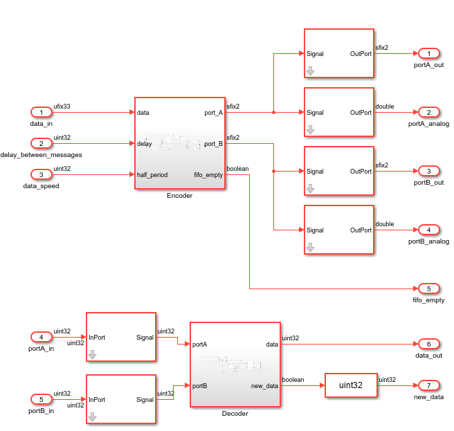
This designs takes the same converter as in the second model and adds another functionnality: converting back the electrical signal, produced by this converter for example, to 32 bits words. The model is split in two main subsystem: the encoder, which is the exact same converter as the one described for the second model, and the decoder, which is presented below.
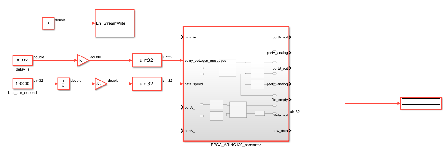
The electrical signal is still put on analog output ports, but also on digital output pins. Indeed the decoder takes as input digital signals, so one way to use this model would be to connect on the NOA the inputs and outputs, to convert back the ARINC words sent by Stream. The output of the decoder is put on a DAQ channel so that the decoded words can be seen on the Simulink interface. The input ports receiving the data through a Stream is the same as before, as well as the two ports controlling respectively the output speed of the data and the time delay between each word.
There are two additionnal output ports: the first one is connected to the FIFO of the encoder and is a boolean indicating whether it is empty. It may be used, in a python script for example (see the Continuous ECG Data Streaming page), to send another series of ARINC words once the previous ones are all converted. The other port is a boolean that indicates when a new word has been converted by the decoder, and may be used for example to set a trigger to catch each decoded word.
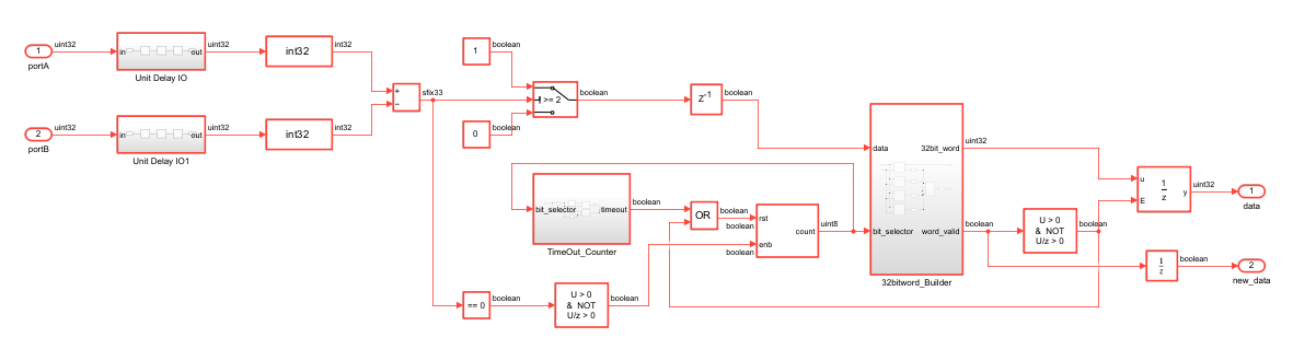
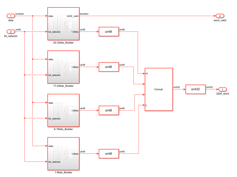
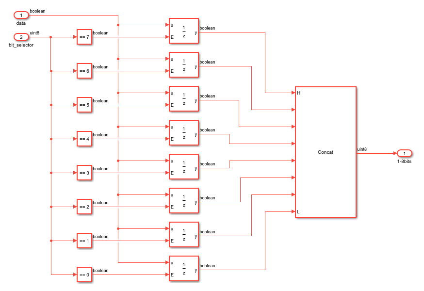
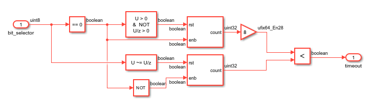
The decoder works in the following way: first the two signals on the input ports A and B are subtracted, as is done traditionnaly with ARINC 429 protocol with the voltages on the two ports. If the difference is more than or equal to two, then the bit encoded is 1, and otherwise it is zero. Then the word is rebuilt using a 0 to 32 counter, which increases when new bits are detected on the inputs, and bit concatenator blocks. The counter is reset if the time between two incoming bits is too long. When the last bit is decoded, the rebuilt word is sent to the data_out output.
For the digital inputs and outputs port, specific blocks have been added: DigitalIn and DigitalOut blocks. They allow the digital signals to be interpreted in the correct format, sfix2 here, since we don't use the default 32 bits of digital signals.
Ports
| Port | Direction | Interface Type | Description |
|---|---|---|---|
data |
input | AXI4-Lite | the ARINC word to convert (uint32) |
data_speed |
input | AXI4-Lite | output speed of the signal; default is 100k bits/sec (uint32) |
portA_analog |
output | Analog Output 0 | the A port of the converted signal, redirected to an analog port (sfix32_En31) |
portA |
output | DAQ Channel 0 | the A port of the converted signal, redirected to the host computer (int32) |
portB_analog |
output | Analog Output 1 | the B port of the converted signal, redirected to an analog port (sfix32_En31) |
portB |
output | DAQ Channel 1 | the B port of the converted signal, redirected to the host computer (int32) |
| Port | Direction | Interface Type | Description |
|---|---|---|---|
data |
input | Stream Input | the ARINC words to convert (ufix33) |
data_speed |
input | AXI4-Lite | output speed of the signal; default is 100k bits/sec (uint32) |
delay_between_messages |
input | AXI4-Lite | time delay between each output word; default is 0.002 sec (uint32) |
portA_analog |
output | Analog Output 0 | the A port of the converted signal, redirected to an analog port (sfix32_En31) |
portA |
output | DAQ Channel 0 | the A port of the converted signal, redirected to the host computer (int32) |
portB_analog |
output | Analog Output 1 | the B port of the converted signal, redirected to an analog port (sfix32_En31) |
portB |
output | DAQ Channel 1 | the B port of the converted signal, redirected to the host computer (int32) |
| Port | Direction | Interface Type | Description |
|---|---|---|---|
data |
input | Stream Input | the ARINC words to convert (ufix33) |
data_speed |
input | AXI4-Lite | output speed of the signal; default is 100k bits/sec (uint32) |
delay_between_messages |
input | AXI4-Lite | time delay between each output word; default is 0.002 sec (uint32) |
portA_in |
input | Digital Input 0 | the A port of the input signal to convert back to a 32bits word (uint32) |
portB_in |
input | Digital Input 1 | the B port of the input signal to convert back to a 32bits word (uint32) |
portA_analog |
output | Analog Output 0 | the A port of the converted signal, redirected to an analog port (sfix32_En31) |
portA_out |
output | Digital Output 0 | the A port of the converted signal, redirected to digital output pins (uint32) |
portB_analog |
output | Analog Output 1 | the B port of the converted signal, redirected to an analog port (sfix32_En31) |
portB_out |
output | Digital Output 1 | the B port of the converted signal, redirected to digital output pins (uint32) |
fifo_empty |
output | AXI4-Lite | indicates whether the FIFO receiving the words from the Stream is empty (boolean) |
data_out |
output | DAQ Channel 0 | the 32 bits word, converted from the signal on portA_in and portB_in (uint32) |
new_data |
output | DAQ Channel 1 | indicates when a new word is decoded and put on data_out (uint32) |
Simulink Interface
First, in the Matlab command window write period = num, where num is the working period corresponding the frequency set later in step 1.4 of the Generation of the Bitstream file process. The blocks in the design work at the period named "period", so it is necessary, to have the design work at the proper frequency.
To implement the second version on hardware, you'll also need to load the matrix in your Matlab workspace, by typing the following code in the command window:
load("arinc_altitude.mat")
Then you'll need to follow the steps in the Generation of the Bitstream file page, to generate the bitstream file and the interface.
Once this is done, the Simulink interface will look like this:
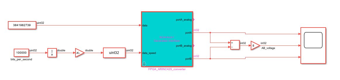
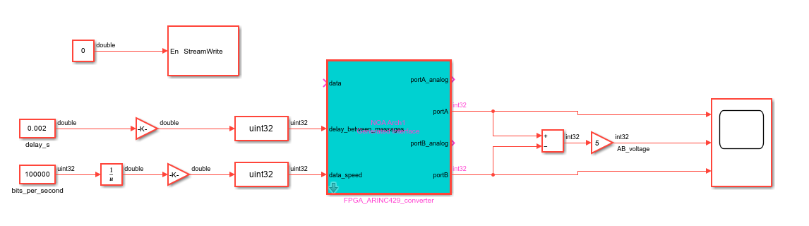
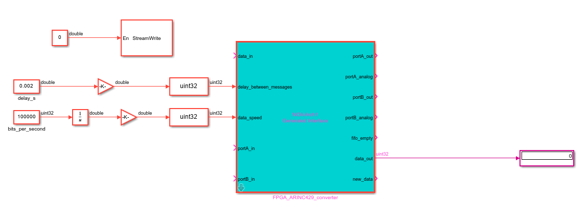
Follow the steps presented on the Connection to the device page. For the third version you need to configurate the digital outputs and inputs to associate them with the physical digital pins of your choice on the NOA (see example below).
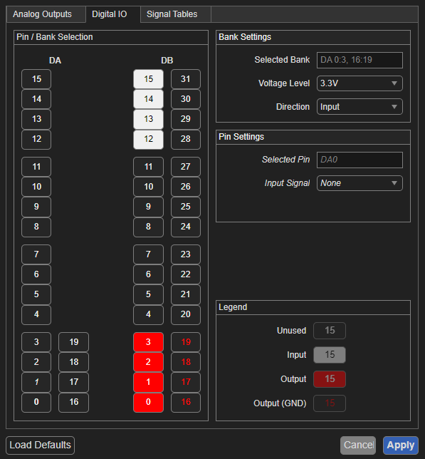
You will be able to visualize in live on the scope (on the right of the interface), the signals produced on your board. You will also be able to visualize them on an oscilloscope, connected to the analog ports of your device, as shown below.
Modifying the constant block linked to data_speed will change directly the output speed of the signal, and in the case of the second version, you can also change the time delay between each message with the constant block connected to delay_between_messages.
In the case of the third version, you will be able to visualize the ARINC words converted from BRZ encoding on the display block connected to the data_out port.
You can change the ARINC word converted by changing the value of the constant block on the left.
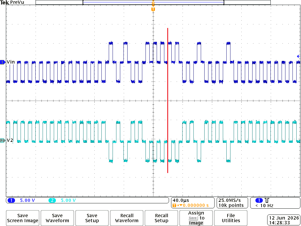
The signal above is the output on port A and the one below is on port B. The red line indicates the end of one word (left of the line) and the start of the next word (right of the line)
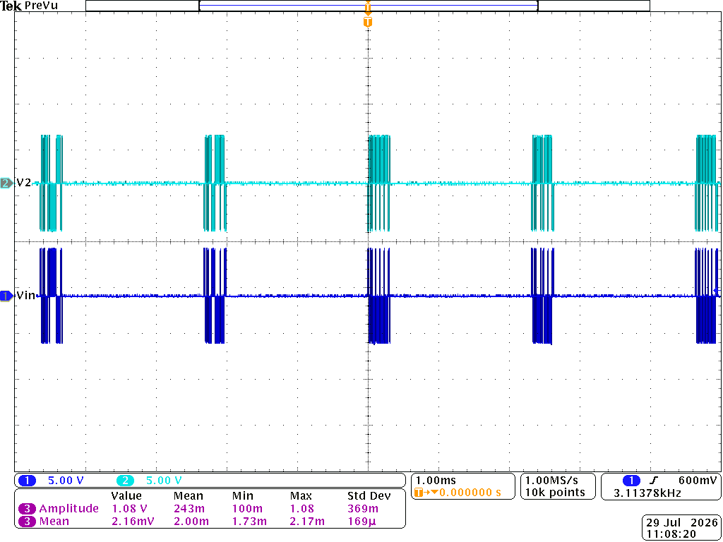
You can start the streaming of the signal, indicated in the StreamWrite block, from the host computer to your board, by changing the value of the constant block on the left from 0 to 1.