Digital Out
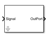
This block outputs a signal onto digital output pins.
The signal can be a single bit (boolean) or multiple (fixed-point types, integers).
Each bit of the signal can then be assigned to a digital output pin before and during model execution in the IO Setup wizard.
Ports
| Port | Type | Description |
|---|---|---|
Signal |
input | the input signal |
OutPort |
output | the output signal, connected to an output port of the FPGA subsystem |
Target Interface
Connection and interface of this block
Directly connect OutPort to an output port of the FPGA subsystem.
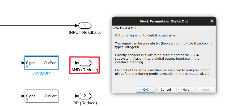
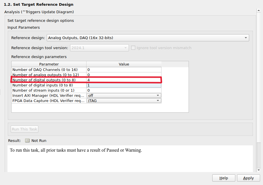
Assign it to a Digital Output interface in the interface mapping (see Generation of the Bitstream file, step 1.3 in the Workflow Advisor; and you need in step 1.2 to choose the number of digital inputs to match your block design).
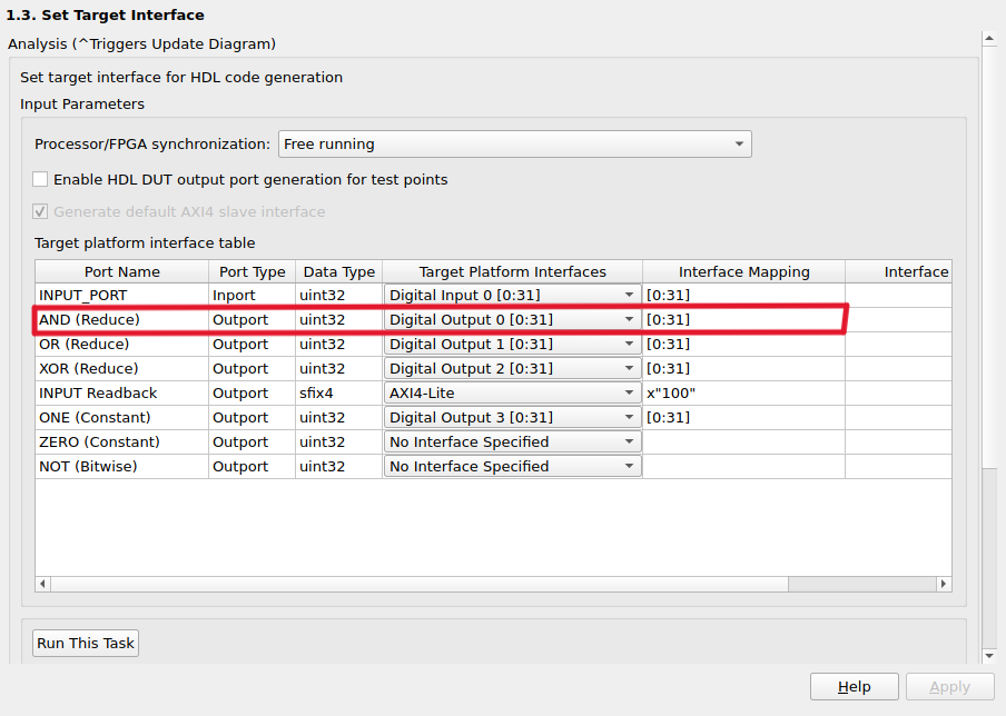
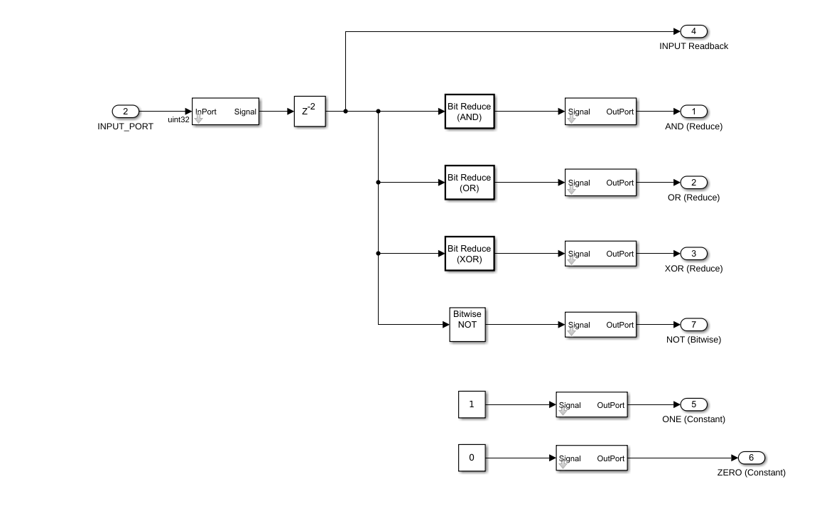
These are taken fom the example design below, operating logical operations on the input signal.