Sine generator
Available at
This example is located in the folder named "sine_generator" and contains 1 Simulink model, named "sine_gen_v1": a FPGA programm able to generate a sine wave.
Info
They were developped for the Eclipse Z7 board, but may be used on NOA Arch 1 as well.
Description
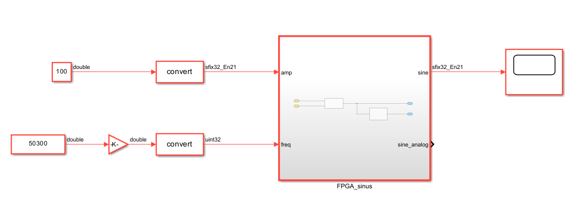
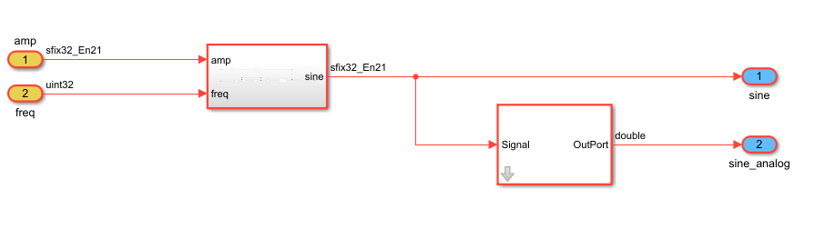
This design has two input ports: one to control the frequency of the sine and the other its amplitude. The signal is then put on two ports: one interfaced to a DAQ Channel, so that it can be seen on a scope on the generated interface, and the other to a physical analog output of the hardware.
For the analog port, an AnalogOut block is used to scale the input signal to the output voltage. The input signal is in a -300 to 300 range and the output voltage is between -3V and 3V (amplitude divided by ten).
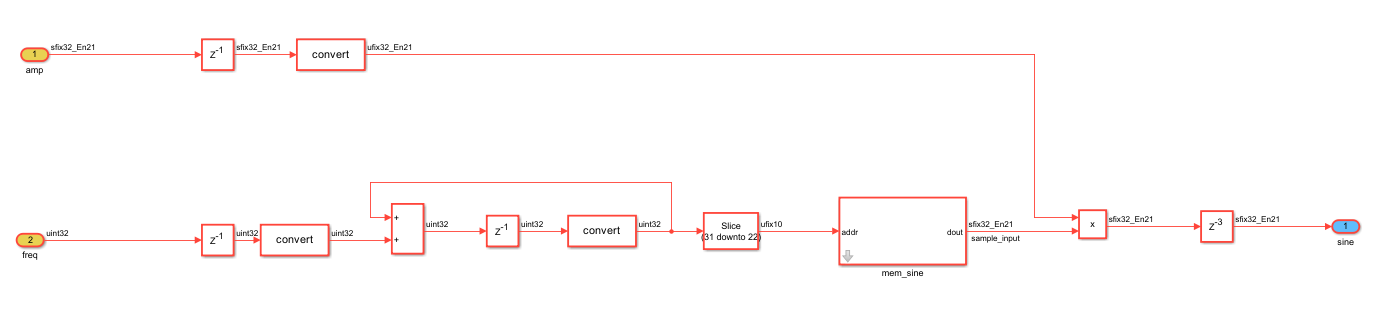
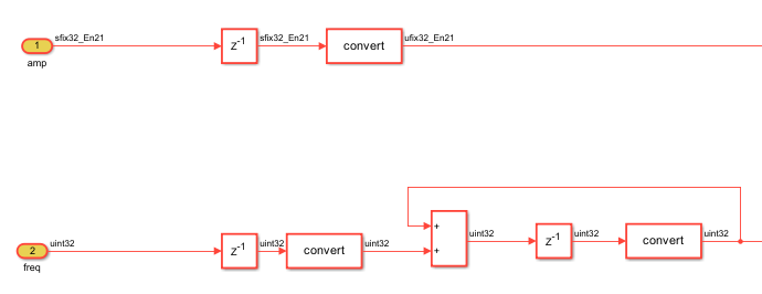
The signal is produced continuously, using a RAM containing values of one sine period (from 0 to 2pi). A counter is used to read these values one by one. The value of the freq port determines the number of counter cycles needed to go from one value to the next, which decides of the frequency of the produced wave. Then it is multiplied by the value of the amp port, to modify its amplitude. Finally it is redirected to the two output ports.
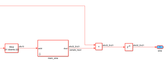
Ports
| Port | Direction | Interface Type | Description |
|---|---|---|---|
amp |
input | AXI4-Lite | the amplitude of the output signal (sfix32_En21) |
freq |
input | AXI4-Lite | the frequency of the output signal (uint32) |
sine |
output | DAQ Channel 0 | the output sine wave, redirected to the host computer (sfix32_En21) |
sine_analog |
output | Analog Output 0 | the output sine wave, redirected to an analog port (sfix32_En23) |
Simulink Interface
First, in the Matlab command window write period = num, where num is the working period corresponding the frequency set later in step 1.4 of the Generation of the Bitstream file process. The blocks in the design work at the period named "period", so it is necessary, to have the design work at the proper frequency.
To implement this design on hardware, you'll need to follow the steps in the Generation of the Bitstream file page, to generate the bitstream file and the interface.
Once this is done, the Simulink interface will look like this:
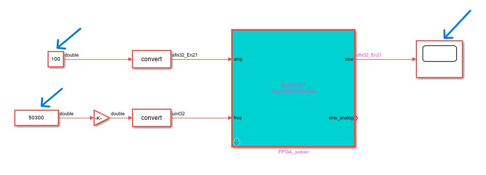
Follow the steps presented on the Connection to the device page, and you will be able to visualize in live on the scope (on the right of the interface), the signal produced on your board (do not forget the settings for the scope).
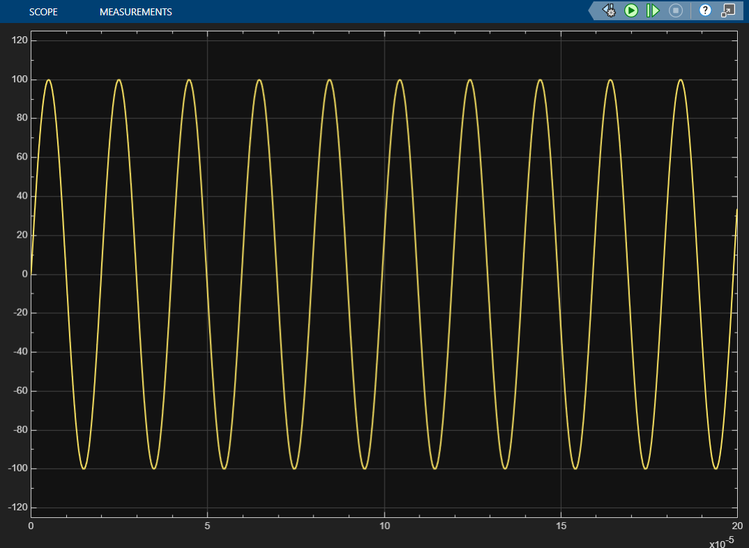
Modifying the two constant blocks on the left will change directly the frequency or the amplitude of the output (in these example pictures, the frequency is 50300Hz and the amplitude is 100).